How do you know the precise moment when your deposition or etching process is completed? How can you tell, with accuracy, that you've etched to a necessary depth, removed a layer or even deposited to a required thickness? The answer is simple: you use endpoints. Here's an introduction to endpoint technology; methods, comparisons, and considerations.
What is an Endpoint?
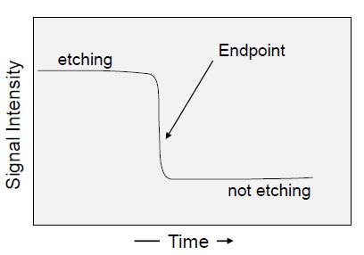
An endpoint is when a process is terminated to provide the desired results. Finding an endpoint uses a set of techniques that provides real-time information about the process being done. For example often, plasma etching involves removing a layer or layers of material in unmasked areas without destroying the layer below. In this case, one monitors the output of the endpoint technology to determine when the layer or layers are removed. Endpoint can also be used during deposition to determine when the desired thickness has been achieved.
Thus, the choice of endpoint technology depends on the process objectives. The objectives can be summarized as:
- When the film(s) being etched is (are) removed.
- When a desired etched depth has been reached
- When a desired thickness of film has been deposited
Regardless of the endpoint technology chosen, there will be measurable outputs that can be used to make process decisions.
Endpoint Goals
The primary goals of utilizing endpoint technology are to achieve:
- Reproducibility: Consistent run-to-run results despite the variability of input material (e.g. different film thicknesses or quality, diverse masking materials, different pattern densities), varying short term process performance fluctuations (e.g. pressure, flow, temp, RF ), and varying long term system changes (e.g. system cleanliness, pumping, calibration drifts)
- Accuracy: Achieving ideal stopping points. Analyzing endpoint performance provides a means for identifying process shifts (e.g. statistical process control) and maximizing throughput by avoiding over-processing time.
By using an endpoint, you achieve accuracy by nature and increased accuracy leads to improved product consistency. A consequence of accuracy and reproducibility is often an increase in throughput. Unnecessary over processing is avoided with good endpoint detection
Selecting an Endpoint Technology
When selecting an endpoint technology, several performance aspects should be considered:
- Non-invasive (not affect the process results)
- Robust and stable (not require frequent calibrations)
- Application appropriate (small pieces, open area, transmissivity)
- Sufficiently sensitive (can detect the appropriate endpoint)
There are two main approaches to endpoint technology; monitoring the wafer and monitoring the system. Each endpoint technology has its strong and weak points and no endpoint system will be suitable for all applications. Beyond the techniques highlighted in this article, other endpoint techniques can be explored, such as ellipsometry, that are typically used in R&D environments.
Wafer Monitoring
Ideally one would want to directly measure what is happening on a wafer. For example, when etching a gate recess on a HEMT device one might want to look at electrical properties such as the source gate current. Although this has been done (ref. 1) it is neither simple nor practical for either R&D or production. An alternative approach uses light sources, typically a laser, for its aiming and brightness attributes, to remotely interrogate the effects of the plasma process on the wafer. This is often referred to as Laser Reflectance or Interferometry.
Laser Reflectance/Interferometry: When an interrogating light source such as a laser is reflected by a substrate the return signal can provide reflectivity and/or interferometric information. The simplest reflective case is monitoring a dramatic change in signal intensity when a reflective metal (e.g. aluminum or chrome) is etched away. This yields the nearly ideal case of a step function from high reflectivity to low reflectivity. Not all cases are this clear and this aspect will be discussed later.
Alternatively, laser interferometry (as opposed to reflectometry) can be utilized to gain insight into what is happening on the wafer. In this case, you would again use an external laser source but would measure for constructive and destructive interference signals generated as the optical path in the material being etched is changing. An example of this approach might be the etching of an optically transparent (to the light source wavelength) dielectric such as silicon dioxide. While the oxide is etching there are reflected light intensity variations that go through maxima and minima corresponding to constructive and destructive interference. One the oxide is etched away the signal flat-lines. The maximum and minimum signals versus time can provide real-time etch rate information as they are related to the optical path-length thickness which is related to the real thickness.
In cases where there are multiple layers of material, the situation becomes more complicated. Because the reflected signal is a superposition of reflections from all the layer interfaces, the intensity of the reflected signal depends on the optical properties of the layers (indices of refraction and transmission). The intensity variation of the signal no longer represents clearly interpreted minimum and maximum but a difficult to interpret intensity that changes as each layer is etched. Another layer of complication is the etch rate for each layer that compresses or stretches the peaks and valleys of the signal. What this means in terms of interpretation is that the peaks and valleys do not align with the interfaces of the layers. This can be modeled but requires a good understanding of the material, optical properties and their etch rates.
The laser approach can also be used in deposition systems to real-time track a film thickness. Just as there is constructive and destructive interference as a film thickness decreases during etching, the same principals apply to a film that is being deposited. In this case, an endpoint based on the layer thickness can be set in the software. When the growing film reaches the setpoint, the system automatically turns off.
Another variation on this laser approach is to replace the laser with the plasma emission as the interrogating light source. This is called optical emission interferometry (OEI).
System Monitoring
There are a variety of system parameters that may change during a process but correlate closely with the changes occurring at the wafer surface. This is more applicable to etching processes than deposition processes where there are different materials that will be etched. As etching occurs and material from the wafer surface becomes volatile, system properties such as the plasma impedance or even the pumping speed (to maintain a setpoint pressure) may change. Monitoring automatic matching network tune and load positions or throttle valve position respectively may provide useful information. However, the most common way to indirectly learn about the etching process is through plasma emission, known as optical emission spectroscopy.
Optical Emission Spectroscopy (OES): The light evolving from a plasma in the chamber depends on the species of materials (atoms, molecules) in the plasma. When plasma species get excited (via collisions with accelerated electrons), they emit a unique spectrum of light — similar to a fingerprint.
By monitoring the intensity of various wavelengths of the emitted light you can determine whether the presence of a species is increasing or decreasing. So as different layers are being etched, the emission from those species is increasing or decreasing and provide evidence of which layers have been etched.
An example to illustrate this capability is the etching of a stack of materials comprised of GaAs and AlGaAs such as might be found in transistors or the Bragg reflector stack of a vertical cavity surface-emitting laser (VCSEL). By monitoring the emission of Ga and that of Al, one can clearly see the Ga signal increase while etching GaAs and decrease during the etching of AlGaAs. The reverse is true for the Al emission signal.
One of the advantages of OES is that the changes in signal intensity correspond to etching through the layers as each layer will contribute etched material that will lead to different signal intensity. Because of this, the intensity versus time signal can be much easier to interpret. Choosing the right atomic or molecular emission to monitor is important and there is software to help develop useful algorithms.
Determining an Endpoint
Although there are applications where the endpoint signal is unambiguous, in practice, there are more cases where there is some uncertainty about where to establish the endpoint threshold. As mentioned, etching using a laser to monitor a single spot during etching of a reflective metal will generate a near-ideal step function. However one must remember that there are other factors involved in obtaining the desired results:
In this example, since the laser is monitoring only a single, small location on the substrate, one might not remove the metal from the entire substrate at the same time if the etch uniformity is not perfect. Since perfection is unlikely, one must understand if the spot on the substrate being measured is etching faster or slower than the other areas. If it is etching more quickly, then it is necessary to incorporate an “over-etch” period to ensure the slower etching areas are cleared.
The lessons from this example can be expanded to include consideration of the original film uniformity. If the film under the laser spot is thinner than the other areas, it will give too early an indication that the etch is complete. Both the plasma processing uniformity and the film uniformity (to be etched or deposited) impact what the endpoint signal looks like. The more non-uniformity, the more sloped the signal.
This uniformity issue is one of the major differentiators between laser-based and emission-based endpoint techniques.
So Which Endpoint Technology Should I Choose?
With most processing questions the most common and truthful answer is “it depends”. This is also the case when choosing an endpoint technology. The table below highlights some of the advantages and disadvantages of the endpoint techniques described in this article.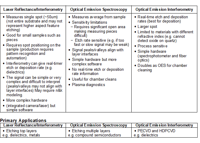
Summary
An endpoint is useful for compensating for process variability. The definition of “endpoint” is determined by the application’s process requirements. For some applications, the endpoint is critical and will affect the device performance. In other applications, the endpoint may not be very critical and an over etch is not going to affect device results. An endpoint can be a very powerful tool for monitoring the performance of a system as it may provide information not only on an individual run but help monitor a system’s performance run-to-run. There are data collection interfaces that accumulate data and analyze it to ensure repeatability.
Reference:
- Lishan, Snider, Hu, "In-situ Device Electrical Parameter Adjustment and Monitoring During Remote Plasma Dry Etching", J. of Vac. Sci. and Tech. B9, 3542 (1991)


